
Making a Game - Visualizing Motion - EP10
by Damien
Video Tutorial
Aims of this tutorial
- Make an arrow point in the direction of the thrust dictated by the plan.
- Make the size of the arrow depend on the magnitude of the planned thrust.
- Design a curved arrow in OpenSCAD.
- Use the curved arrow to represent torque from the plan in the same way we did for the linear thrust.
- Create a simple shader for the arrows.
Getting the direction of the thrust
We cannot simply use the Cartesian coordinates for the arrow because the rotation property requires Euler angles. Rather than dealing with the headache of Euler angles and their non-commutative property, I change my coordinate system to a modified spherical polar coordinate system. Since we are dealing with a normalized vector, r=1. We can then define phi in the usual way and theta as the angle from the z-x plane as opposed to the y axis. This small change will make our life easier later on when we transform the arrow into the required rotation. Below is a diagram of the coordinate system with Cartesian coordinates as a reference.
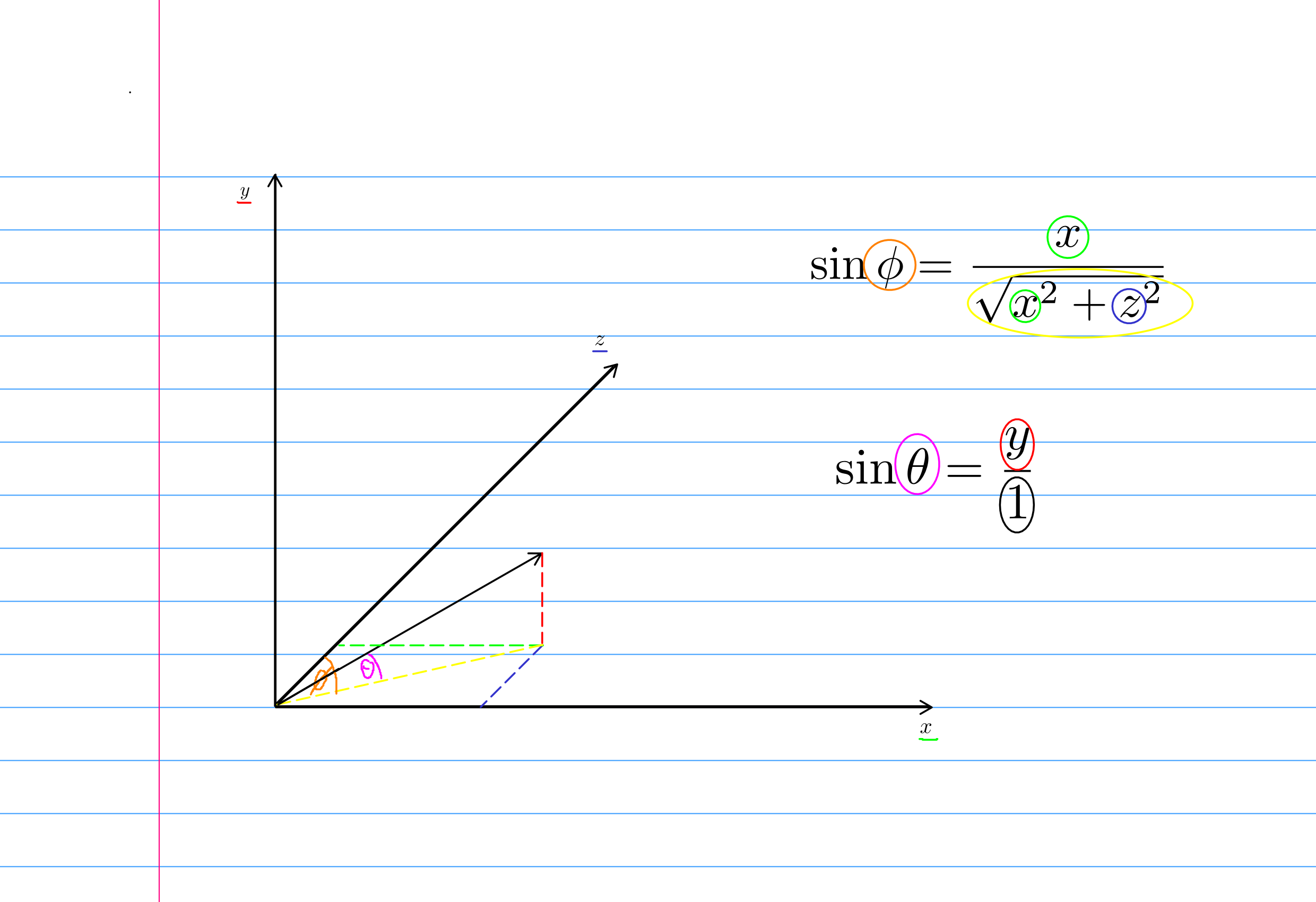
We can take the arcsin of the above formulas to find the required angles and then make the relevant rotations using those angles (make sure to use local coordinates when making the second rotation or you will end up rotating in the wrong direction). The size of the arrow is easy, we can simply take the magnitude of the thrust vector and scale the arrow by that factor!
Now how do we apply those rotations? We cannot simply apply them to the arrow because the arrow will clip into the spaceship. In order to correctly scale and rotate the arrow, we need some containers for the arrow. These will be spatials that can be rotated and scaled. We will have the arrow at the origin of a spatial that can be scaled which will be at an offset of another spatial that can be rotated and then that spatial will be at the origin of the player object.
Designing a curved arrow in OpenSCAD
The first thing to do when designing something in any CAD software, is consider what shapes you could use to construct the object. The simpler the shapes, the easier it will be. For a curved arrow, we can use a torus through an angle of ~300 degrees and an arrowhead which will simply be a cylinder approximating a cone by setting one of the radii to ~0.
For the 'stick' part of the arrow, we first need a circle (circle(r={radius});). We can then translate this circle along the x axis (translate([{x},{y},{z}]);), making sure that the translation is more than the radius of the circle so that after revolving, we have a hole in the middle where the spaceship can go. Finally, we can do a rotate_extrude(rotate_extrude(angle={angle});), also known as a revolve in many other CAD software. In OpenSCAD, a rotate_extrude will always be around the z-axis. This is not a problem in this case, but in other cases, you may need to transform the object before and after the rotate_extrude.
For the arrowhead, we need a cone which is a special case of a cylinder (cylinder(r1={base_radius}, r2=0.0001, h={height});). We can then transform it to the correct position using the previous angle, the rotate and translate transformations. Once you are satisfied with the design, you can optionally make a union of the objects (union{object1; object2;};) and then export it as an stl. Remember to compile it first with F6. Once that is complete you then need to turn it into an obj file. We can use blender in headless mode for this (make sure your startup file is empty or you will get a cube in the middle of your model). Here is a script to make the convertion (run with blender --background --python <file_name> -- in.stl out.obj):
#!/bin/python

import bpy
import sys

argv = sys.argv
argv = argv[argv.index("--") + 1:] # get all args after "--"

candidate_list = [item.name for item in bpy.data.objects if item.type == "MESH"]

# select them only.
for object_name in candidate_list:
  bpy.data.objects[object_name].select()

# remove all selected.
bpy.ops.object.delete()

stl_in = argv[0]
obj_out = argv[1]

bpy.ops.import_mesh.stl(filepath=stl_in, axis_forward='-Z', axis_up='Y')
bpy.ops.export_scene.obj(filepath=obj_out, axis_forward='-Z', axis_up='Y')
You can now follow the same steps that we covered for the linear arrow for the rotational arrow!
Creating a shader for the arrows
I want a glassy texture for my arrows. This will be quite computationally expensive since we need refraction effects which are not easy to compute. To do this create a new material, enable transparency in the flags, and turn on transparency in the transparency tab. I recommend turning down the roughness to an extremely low value because glass is smooth. Now set the albedo to a colour you like and make the alpha low (0 will be perfectly clear glass). We also want to enable refraction and put the strength up to about 0.5 (refractive index of glass is about 1.5). If you wish, you could give it some glow with the emission tab.
Now for our new shader to really shine, we need to create an environment node in the root node. Here we can set a bunch of options that will make our scene look better like depth of field, glow, fog and a bunch of post processing options. Go ham experimenting with what you like in there and have fun!